The fixed surface of the screw is meant to properly operate the valves. The spring loaded ball protrudes beyond the normal tip length with the intent of absorbing the valve lash gap to keep the valvetrain quiet.
The concept is interesting, but having unknown quality, I'd be concerned with the springs possibly holding the valves open a bit and burning valves or ultimately if they wear long term, that springs and balls could fall out and create a mess.
Always cool to see some of these old school aftermarket items though...
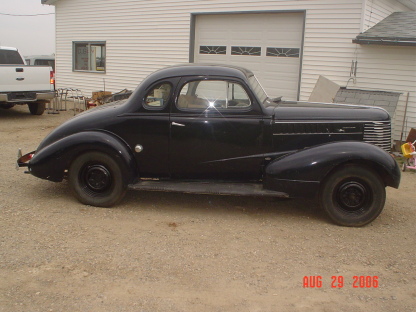
1938 Canadian Pontiac Business Coupe (aka a 1938 Chevy Coupe with Pontiac shaped front sheet metal - almost all Chevy!) 1975 4-speed L82 Vette
I have/had a set of those guys. They are supposed to make your engine quieter than a mouse. I fouund tey make it difficlt to adjust the valves to my satisfaction. Never quite sure where you were at....and noise level never seemed to change..
What I found that was more effective was hollow push rods and a canvas cover pad on top of the rocker arms.
Interesting design for a mechanical adjuster. I can understand Gene's comment about trying to determine actual clearance. It is really an attempt to mechanically provide the slight "give" in a hydraulic lifter.
There is one feature I noted on the instruction sheet. The design of the spring loaded ball and the rounded end of the adjuster is such that the ball will only collapse a certain distance until the the rounded end of the screw bottoms out in the seat in the push rod.
My guess is that you are basically forcing that condition when you turn the adjuster screw with "FRIM downward pressure on the screwdriver". If you then remove the feeler gauge the rocker arm moves slightly when the spring pushes the ball down. That removes the operating clearance between the rocker arm tip and the top of the valve stem.
I assume that the spring load on the ball is fairly small compared to the spring load on the valve. The rocker arm tip is always in contact with the top of the valve stem. When the lifter starts to move up the first action is that the ball is pushed up into the adjuster until the rounded end of the adjuster seats in the push rod. Then the valve starts to open.
Or that is at least the theory!
Even if the spring in the adjuster fails the valve will still open. There will be a larger operating clearance so it will be noisy. It looks like the ball would be captive in the push rod socket until you take things apart. I would definitely want a to have magnet right there to catch the ball and pieces of spring.
There are 2 design variables to consider: - How far does the ball move before the rounded tip bottoms in the seat on the push rod? If it is more than the valve clearance you set then the valve does not open to maximum. - What is the spring load on the ball compared to the spring load on the valve?
My thinking would be that you would have to adjust these with the engine hot but not running. It would definitely mess up your feel of tension on the feeler gauge if the engine was running.
Here is another interesting idea about how to adjust them. Do it the way we do hydraulic lifters. With the engine running simply turn the screw until the ticking noise just stops. Rather than continue turning like we do to center the lifter in its bore, stop and lock the adjuster. That means there is no clearance between the rocker arm tip and valve stem. The greater force of the valve spring will overcome the load on the ball so the valve will close.