|
|
Joined: Aug 2005
Posts: 123
Shade Tree Mechanic
|
OP

Shade Tree Mechanic
Joined: Aug 2005
Posts: 123 |
Yes, I have the wiring diagrams, and I have tried and tried to wire the signals up like the diagram, but I still can't get them to work. I just can't see the forest for the trees.
First, I HAVE CONVERTED FROM 6 TO 12 VOLTS, CHANGED ALL LIGHTING TO LED, , INSTALLED ALL NEW 12 VOLT GAUGESI, followed the color of wires, but still can't get the signals to work. and by the way my brake lights don;t work now. There is power to the brake light switch, in and out. ?? Anyone can help. I am just missing something and just can't figure it out. I can go into detail more if anyone has any ideas.
John
|
|
|
|
|
Joined: Dec 2016
Posts: 656 Likes: 3
Oil Can Mechanic
|
|
Oil Can Mechanic
Joined: Dec 2016
Posts: 656 Likes: 3 |
Pretty much everything I said over in this thread applies to you, too. https://vccachat.org/ubbthreads.php/topics/420914/re-diectional-signals.html#Post420914You probably wont have the guide 6004 switch, but whatever you do have (it's probably built into the steering column) will work the same. If you have a 2 separate arrow indicators in your dash (for right and left), then you can ignore the part about the third pin on the flasher (and the light). When you have 2 separate dash indicators, they just connect to the front signals. In that case, the third pin on the flasher is not used. On 12v flashers the third pin is often missing entirely. Traditional flashers rely on current drawn by the bulbs to make the flasher flash. You will probably need a special flasher to get things flashing with the LED bulbs, as they don't draw enough current to make the traditional one work. Good luck.
Last edited by bloo; 02/04/19 01:19 AM.
|
|
|
|
|
Joined: Dec 2007
Posts: 4,024 Likes: 99
ChatMaster - 4,000
|
|
ChatMaster - 4,000
Joined: Dec 2007
Posts: 4,024 Likes: 99 |
I agree that a traditional make & break relay style flasher will probably not work with the low current draw of LED bulbs.
One simple test is to connect a hot wire directly to the wires going to the turn signal bulbs. This will bypass the flasher and column switch to make sure the bulbs are working.
Rusty
VCCA #44680
|
|
|
|
|
Joined: Jan 2002
Posts: 30,701 Likes: 141
ChatMaster - 25,000
|
|
ChatMaster - 25,000
Joined: Jan 2002
Posts: 30,701 Likes: 141 |
I have LED bulbs on just the rears of my 1950. The signals work OK but the piolet light on the signal switch does not light-up. I would guess if I were to install LED bulbs if the front there would be no flash at all. They do make some kind of eletronic flasher for this use.
Gene Schneider
|
|
|
|
|
Joined: Oct 2004
Posts: 535
Oil Can Mechanic
|
|
Oil Can Mechanic
Joined: Oct 2004
Posts: 535 |
The original flashers depended on the higher current draw of incandescent bulbs to flash. There are flashers for the low current LED bulbs, but they all seem to be for 12 volt systems. For 6 volt systems, The Filling Station sells resistors (AF-572 - requires 2) to "load" the circuit so the flasher will work with LED bulbs. Chevs of the 40s sells WASL52DL2 (1 required) to do the same thing.
|
|
|
|
|
Joined: Aug 2005
Posts: 123
Shade Tree Mechanic
|
|
OP
Shade Tree Mechanic
Joined: Aug 2005
Posts: 123 |
The flasher isn't the issue in my case, I have a new flasher unit for LED, my problem is the connection of wires , following the diagram from the service manual, I can't get them to work. I know I'm overlooking something.
John
|
|
|
|
|
Joined: May 2002
Posts: 6,149 Likes: 42
ChatMaster - 6,000
|
|
ChatMaster - 6,000
Joined: May 2002
Posts: 6,149 Likes: 42 |
My local auto electric parts shop in Aus had a 6v flasher unit can that is suitable for LED lights but I cant suggest where they are available in the US.
Tony
1938 1/2 ton Hope to drive it before I retire
|
|
|
|
|
Joined: Nov 2001
Posts: 29,863
Tech Advisor ChatMaster - 25,000
|
|
Tech Advisor ChatMaster - 25,000
Joined: Nov 2001
Posts: 29,863 |
The Mangy Old Mutt
"If It's Not Junk.....It's Not Treasure!"
|
|
|
|
|
Joined: Dec 2007
Posts: 4,024 Likes: 99
ChatMaster - 4,000
|
|
ChatMaster - 4,000
Joined: Dec 2007
Posts: 4,024 Likes: 99 |
Hi John,
Sounds like there is some confusion regarding the actual wiring of the circuits. Can you post some pictures or share some links to the wiring diagrams you are using?
Also, one approach I use to deal with wiring problems is to set up the circuit on the shop floor or work bench temporarily before I install it in the car. That way I now that all my components work and I have a good idea of what connects where.
I have had more than one situation where using the color of the wire did not give the right wiring. This is especially true when you are mixing and matching parts from various suppliers. I use masking tape to tag circuits in those situations.
Rusty
VCCA #44680
|
|
|
|
|
Joined: Aug 2005
Posts: 123
Shade Tree Mechanic
|
|
OP
Shade Tree Mechanic
Joined: Aug 2005
Posts: 123 |
Thanks for the response, you are right there is some confusion in the circuitry, first let me say, I am using the wiring diagram that is in the chevy manual for 1954, not much there but it shows the wiring and color codes. This is a stock wiring for 54, I think 53 is about the same. The confusion comes from my replacement of all the instruments , upgrading to 12 volts. somewhere along the line the wires for the flasher unit disappeared, all except the yellow wire going to the column, the pink wire that went to the ign side of the gas gauge,(according to the diagram) was dangleing, so I opted to fuse it and attach to a power source , then I came to the black wire which according to the diagram was linked to the wires going to the indicators, I assume the dash directional lights. Which I did, nothing no lights or flashing. I bought a LED flasher, but that didn't help. Also, my brake lights don'work. I know the orange wire from the headlight switch goes to the brake switch,from that a white wire goes to the column. Both wires are hot.
I would take pictures, but fts a little difficult to take under the dash. I know this is a long explanation but maybe you can see something that I can't. on the off chance that the flasher is bad, I purchased another one yesterday and will try it this morning. After I shovel snow and get a fire started in the shop. thanks, John.
John
|
|
|
|
|
Joined: Dec 2016
Posts: 656 Likes: 3
Oil Can Mechanic
|
|
Oil Can Mechanic
Joined: Dec 2016
Posts: 656 Likes: 3 |
Is this a 1954 car or a 1954 truck?
Is your turn signal switch built into the column, or is it a separate "pod" thing?
Do your brakelights share bulbs with the rear turn signals or do they have separate bulbs?
Is the wiring diagram you are using online somewhere?
Is there a separate right and left "tattletale" blinker to tell you the signals are on? Or just one that blinks for both right and left?
How many pins on your flasher?
Do the signals light up and not blink or just not light up at all?
Last edited by bloo; 02/06/19 01:34 AM.
|
|
|
|
|
Joined: Aug 2005
Posts: 123
Shade Tree Mechanic
|
|
OP
Shade Tree Mechanic
Joined: Aug 2005
Posts: 123 |
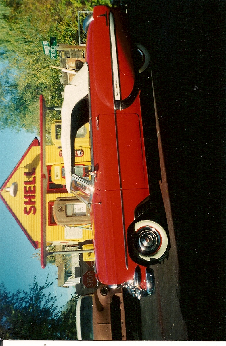
My vehicle is a car, 1954 Bel Air Convertible
The turn signals are built into the column
I guess you could say the brake lights and tail lights are built into the same unit, as it is a LED one piece unit, purchased from The Filling Station. the tail lights work great, if you switch the wires the unit is brighter (brake light circuit), and the front parking lights work great, I have LED bulbs in them also.
The wiring diagram I'm using is out of the service manual for 54. I also have an excerpt from a chevrolet passenger car wiring diagrams for complete chassis ,(reprint) I have copied the diagram on my printer and enlarged it for my eyesight, and traced the lines to their respective point.Also, someone downloaded a copy of the 53 diagram in this discussion .
There are dash lights in the instruments that are supposed to come on when applying the switch. I have managed to have them light up at the same time when applying the handle for left turn. they both stay lit and don't flash. Nothing out of the flasher (clicking)
I have a 3 pin flasher (LED)
I The dash lights will light up at the same time when I touch the black wire to one of the dash lights.
John
|
|
|
|
|
Joined: Dec 2007
Posts: 4,024 Likes: 99
ChatMaster - 4,000
|
|
ChatMaster - 4,000
Joined: Dec 2007
Posts: 4,024 Likes: 99 |
Hi John,
I know how frustrating it can be to track down wiring problems. And it can be tricky trying to troubleshoot them through a forum such as this.
Here are some suggestions to keep you going. It is best to do them in the sequence I listed them.
- Make sure you keep going back to the basics as you work through each circuit. Confirm that you have continuity from end to end of each wire. Make sure each switch works as expected.
- Do not rely on wire color! Trace each wire end to end with a ohm meter and label each end with the same number. Perhaps the wiring harness has been replaced. You have not shared any history of the wiring work done when the car was converted to 12 volts.
You noted that the rear lights have one bulb that has 2 levels of brightness.
- This means the lower light level will be the running light (or tail light). That level of brightness should be on whenever the light switch is in the parking light or headlight position. For wiring purposes the wiring for the instrument panel (dash) lights should be connected to that same function on the headlight switch. The dash and tail lights should be on whenever you have either the parking lights or headlights turned on. Get these working properly first.
- The brighter light level is for the combined brake light/turn signal function. When you press the brake pedal that should send power to the brighter portion of the tail light. Make sure you have that function working correctly before you go back and work with the turn signals.
- The trickier part is that the turn signal function also uses the brighter light level. That means there are some connections between the brake light wiring and the turn signal switch. Consider this. The brake lights need to come on when you press the brake pedal even if you are not indicating a turn. The turn signals need to work even though you do not have your foot on the brake. And when you step on the brake while the turn signal is on you expect the other brake light to come on steady.
My best guess is that the wiring among the headlight switch, the brake light switch, the flasher, and the turn signal switch is the source of your problem. A starting point is to use your ohm meter and check the function of each of those components. If one of them is not working you will never get things wired correctly.
Hope this helps!
Rusty
VCCA #44680
|
|
|
|
|
Joined: Dec 2016
Posts: 656 Likes: 3
Oil Can Mechanic
|
|
Oil Can Mechanic
Joined: Dec 2016
Posts: 656 Likes: 3 |
Lots of good advice from Rusty 37 Master in that last post. Consider this. The brake lights need to come on when you press the brake pedal even if you are not indicating a turn. The turn signals need to work even though you do not have your foot on the brake. And when you step on the brake while the turn signal is on you expect the other brake light to come on steady. ^^This the key to understanding how it works. When the "bright" function of a bulb (as Rusty put it) is used for both Brake and Signal, the brake light wiring has to go through the turn signal switch. The rears are completely separate switching from the fronts and the dash indicators. 12 volts goes to the brake light switch. The other terminal is wired to the signal switch. This voltage is sent back out to the 2 rear bulbs (on 2 different wires) while the turn signals are OFF. When you turn a signal on, the turn signal switch will disconnect one rear bulb from the brake lights, and connect it instead to the flasher. Now, about the fronts..... Make sure you have the flasher wired right. Maybe your new one has a different pin pattern than the old one? Maybe the maker can tell you which pin is which. It matters. 12v goes to one pin of the flasher. The voltage comes out another pin and goes to the turn signal switch. With the signals off, that is as far as it goes. The 2 front signal bulbs are connected to the turn signal switch on their own wires. When you turn a signal on, it will connect one of them to the flasher. I would get that much working before worrying about dash indicators. If the dash indicators are 2 separate bulbs with 2 separate wires (it sort of sounds like it in your post above), then just connect them to the front signals (not the back signals, because if you do, they will come on with the brake lights). If the dash indicators are meant to come on together, then they get wired to the third flasher pin instead. The third flasher pin (on on original flasher) is meant to flash no matter which side is on.
Last edited by bloo; 02/06/19 04:40 PM.
|
|
|
|
|
Joined: Aug 2005
Posts: 123
Shade Tree Mechanic
|
|
OP
Shade Tree Mechanic
Joined: Aug 2005
Posts: 123 |
I will say this so far I have the lights working, when I position left the left lights go on, when I position right the right side goes on. However both dash lights ,light up., and don't flash.
I have heard, that it might be necessary to place an resister in the circuit for brake lights, any comments on that.
Oh and by the way still not brake lights., so I am going to follow the suggestions presented here by Rusty37 and Bloo. thanks guys I'll keep plugging along.
John
|
|
|
|
|
Joined: Dec 2016
Posts: 656 Likes: 3
Oil Can Mechanic
|
|
Oil Can Mechanic
Joined: Dec 2016
Posts: 656 Likes: 3 |
Ok, I found a scan of the wiring diagram Online. Unfortunately it is a blurry scan and I can barely read it. http://chevy.oldcarmanualproject.com/shop/1949_53/13supplement/13-29.jpgIf I am reading it right, it makes no sense. Maybe the diagram has mistakes? I suspect this black wire you mentioned coming from the dash indicators needs to be grounded. Here is how I think it is (subject to change if someone can come up with a readable diagram). Light blue seems to go to the left front and the left indicator Dark blue seems to go to the right front and right indicator Pink seems to go to the left rear (brake and signal) Purple seems to go to the right rear (brake and signal) That makes sense, and then..... ???????? color? wire goes from the headlight switch to the brakelight switch (power for brake lights) White goes from the brakelight switch to the signal switch and then.... ??????? another color? wire goes through a fuse to the flasher. looks like they picked up the power at the gas gauge? (power for the signals). Yellow wire carries "flashed" 12v from the flasher to the signal switch. Now, here's the weird part: It looks like the dash indicators, instead of being grounded on the ground side, come BACK on a black wire, which was apparently connected to the third pin on the flasher. I don't know what they were up to there. Maybe some kind of scheme to detect bad bulbs? I strongly suspect this wire will need to be grounded. Perhaps others can comment.
Last edited by bloo; 02/07/19 01:20 AM.
|
|
|
|
|
Joined: Jan 2002
Posts: 1,069 Likes: 9
ChatMaster - 1,000
|
|
ChatMaster - 1,000
Joined: Jan 2002
Posts: 1,069 Likes: 9 |
You might get a wiring diagram from Classic Wiring. They have large laminated and colored diagrams. I have on for both my 48 and 46. Easy to read. https://www.classiccarwiring.com/
1946 Chevy 3100 1/2 Ton Pickup Purchased 11/18/17 Sold 9/20
1948 Chevy Fleetmaster Coupe, Purchased 6/20/2010
1965 Chevy ll 350 Purchased Feb 2021. 3-speed Saginaw Hurst Floor Shifter 3.08 Rear End
2019 Ford Ranger Lariat Super Crew
|
|
|
|
|
Joined: Jan 2002
Posts: 30,701 Likes: 141
ChatMaster - 25,000
|
|
ChatMaster - 25,000
Joined: Jan 2002
Posts: 30,701 Likes: 141 |
The directional switch wireing is in the 1949-1953 shop manual and in the 1954 supplement. The signals were a required i option in 1953 and 1954 and had the same wiring, etc.
Gene Schneider
|
|
|
|
|
Joined: Aug 2005
Posts: 123
Shade Tree Mechanic
|
|
OP
Shade Tree Mechanic
Joined: Aug 2005
Posts: 123 |
i ORDERED ONE THIS MORNING, HOPE ITS BETTER THAN THE ONE i'VE BEEN USING. THANKS
John
|
|
|
|
|
Joined: Aug 2005
Posts: 123
Shade Tree Mechanic
|
|
OP
Shade Tree Mechanic
Joined: Aug 2005
Posts: 123 |
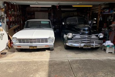
Whoops, my picture came out sideways, How do I fix that,?
John
|
|
|
|
|
Joined: Dec 2016
Posts: 656 Likes: 3
Oil Can Mechanic
|
|
Oil Can Mechanic
Joined: Dec 2016
Posts: 656 Likes: 3 |
|
|
|
|
|
Joined: Aug 2005
Posts: 123
Shade Tree Mechanic
|
|
OP
Shade Tree Mechanic
Joined: Aug 2005
Posts: 123 |
Thanks, I will be glad when I get the turn signals and brake light working
John
|
|
|
|
|
Joined: Dec 2007
Posts: 4,024 Likes: 99
ChatMaster - 4,000
|
|
ChatMaster - 4,000
Joined: Dec 2007
Posts: 4,024 Likes: 99 |
Hi John,
Sounds like you are making some progress. I expect that a higher quality picture of the wiring harness will help.
Please remember that you need to trace the actual wire end to end to confirm where it should connect. The temptation is to use the color designations as shown in the diagram. I have had multiple situations when the actual wiring on the car did not correspond to the diagram especially with respect to color. This has happened for many different makes and many different years. I think it is even worse with the massive wiring harnesses on newer cars.
The wiring diagram is the design that the engineering group released for production. What was actually built is often a different story. For example, if the wiring harness supplier was out of a certain color and gauge of wire, they would substitute a different color in order to keep production going. In other cases the diagram might have been revised but the revised diagram was never published in the service information. Or someone did a service repair and completely replaced a wire with whatever they had.
Rusty
VCCA #44680
|
|
|
|
|
Joined: Aug 2005
Posts: 123
Shade Tree Mechanic
|
|
OP
Shade Tree Mechanic
Joined: Aug 2005
Posts: 123 |
I'm not making it any easier for the next owner either, by replacing all of the dash instruments , radio, etc there won't be a diagram to match what I have done. All of the new items under the dash take up a lot less room, but for example, the dash instruments hot wires are all red, that's OK, but the ground wires are blue . If I get time I might draw up a diagram and leave it in the glove box.
Anyway I'm still plugging away, getting closer, all lights are working , picked up some resisters yesterday , will connect to taillights and see if the flasher will work.
John
|
|
|
|
|
Joined: Aug 2005
Posts: 123
Shade Tree Mechanic
|
|
OP
Shade Tree Mechanic
Joined: Aug 2005
Posts: 123 |
well things haven't improved a lot; I received the color diagram , its easier kto read but it didn't change the information I already had.
Here is the latest. I have all lights working, that's taillight, headlights, parking lights, and when I turn the headlights on the dash light indicators light up, both of them, but no signals. No brake lights. If I go to the brake switch and connect both wires the brake circuit will light up the taillights., ( I ordered a new brake switch in case this one is bad).
Now the flasher, I have tried 3 different ones, including the original.,
Here is the what the diagram shows; X = power, (pink wire fused to ign),
L= to turn signal switch, and P= Ground to left and right indicators. Nothing, power should be going from x to L, nothing
John
|
|
|
|
|