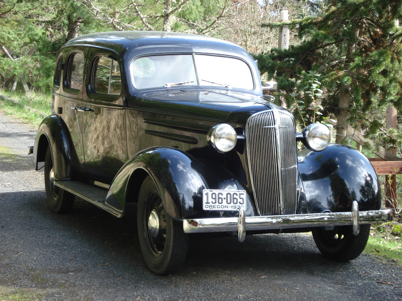
6 volt 1941 Chevy Master Deluxe 216 generator etc.
Installed an original horn over the winter. If the car is idling it will pitifully attempt to beep. Giving the engine any RPMs and it works. Sending current to it from the battery and it beeps no issue. Did we wire something wrong? I would have thought that regardless of when it was beeped it should have been at the same volume. Checked the ground. Currently using a starter switch for a tractor since it fit an existing hole in the dash (will do this right in the future, wanted to get the functionality first. Hole was already there we just removed what looked to be a factory plug).
I have found that having an old car is a constant project that is never done. I think that is a good thing. Keeps me learning new things. Having two from different eras is just a form of higher education.
Keep in mind that at idle your generator isn't charging enough to fully power most electrical demand. That's one reason I converted to a 6v alternator. Horns pull a lot of amps. It doesn't surprise me that it barely honks at idle.
VCCA Member 43216 Save a life, adopt a senior shelter pet. 1938 HB Business Coupe 1953 210 Sedan
Check the wiring diagram for your car. If I remember correctly it is on a direct circuit back to the battery. It does not even go through the ammeter due to the high current draw.
I am assuming that you have the single horn that is mounted on the intake manifold. If you have the accessory dual horns you definitely need a relay. It was part of the kit.
I am going to look at adding a relay. I have to check how we wired it in. I know it cannot be through the ammeter as that does not drop when it is pressed. I also know it is not going directly to the battery on its own circuit.
We are once again looking at a growing list of things to fix. Old car story, the more you think you have completed the more things you find to be fixed. A old car is never done.
I have found that having an old car is a constant project that is never done. I think that is a good thing. Keeps me learning new things. Having two from different eras is just a form of higher education.
Ours is wired to the battery side of the ammeter. For the horn switch we are using a starter button from a tractor that was the same size as an existing hole in the dash. (temporary until we have the parts for the steering wheel, yes a long and growing list). Shorting out the wire and not using the button produces the same result.
I thing making a dedicated circuit would be best at this point to correct this. Since it is technically working we are placing it on the list but not sure when we will get back it. Thanks for helping to diagnose it.
I have found that having an old car is a constant project that is never done. I think that is a good thing. Keeps me learning new things. Having two from different eras is just a form of higher education.
From my experience original cars with two horns mounted in front of the radiator should have a relay screwed to the firewall directly below the voltage regulator. For 6 volt, power(10 or12 gauge) comes from a wire spliced into the starter ammeter wire. I’m going from memory but believe it is actually a parallel splice soldered. The connects to the center relay terminal. Horns and and ground wire from steering wheel connect to the other two relay terminals. When I get home later today I’ll verify. Also I believe there might be a different wiring diagram
12 awg was used. We did use a ring to connect it to the post on the ammeter. It stated it was rated for the amperage but perhaps that is an issue.
I have found that having an old car is a constant project that is never done. I think that is a good thing. Keeps me learning new things. Having two from different eras is just a form of higher education.
Attached are some pictures of the original factory installation. You can see the the parallel splice in the picture showing the center of the firewall. According to the hand written notes I made when I disassembled and measured an original harness, 10 wire gauge was used to power the relay. The wire to the horns was also 10 gauge but had a short length of 12 gauge with a parallel splice near the end to supply the other horn. By the way, also attached is a picture of the wiring diagrams in the shop manual. From my experience I believe the labels on the truck/passenger car diagrams are reversed.
It appears I left a sentence off my previous post. I should have mentioned that the factory relay was screwed to the firewall below the voltage regulator and fed from a parallel splice in the wire between the starter and the ammeter.